.png)
.png)
.png)


.png)
When using diamond drilling from the surface to collect geotechnical data, the number of drill core samples available at the tunnel level is related to the drill hole spacing. Therefore, as geological and geotechnical data is only retrieved from a limited part of the tunnel, inaccurate interpretations can occur and lead to problems if unexpected rock conditions are encountered during excavation.
To enhance data coverage, Directional Core Drilling (DCD) can be employed to guide the drill holes to the planned tunnel level and align with the tunnel path, enabling continuous core sampling along the planned tunnel trajectory. This significantly improves the density of data and the chances of gaining a complete understanding of rock mass conditions prior to construction.
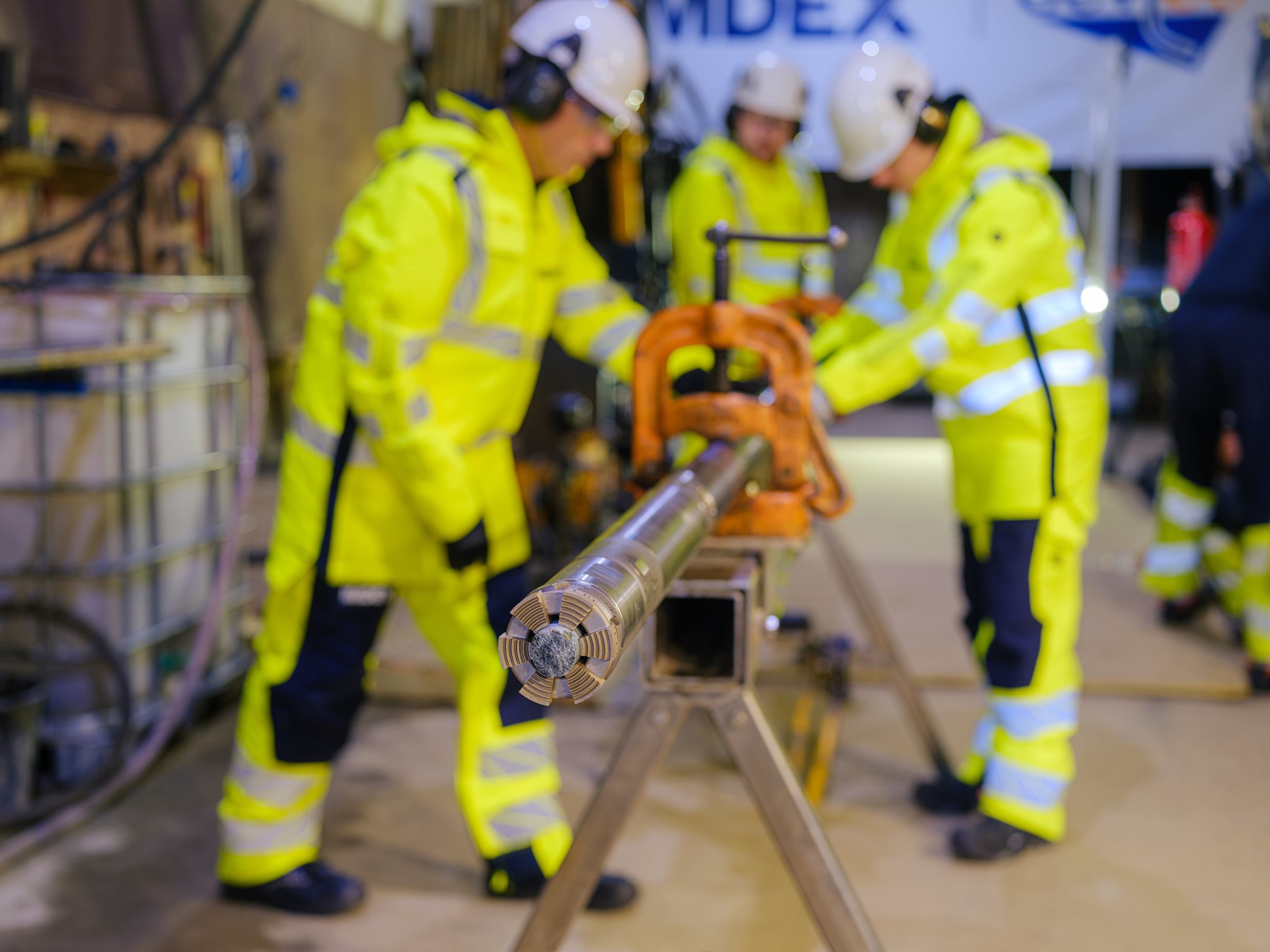
This article presents a case study from Anglo American’s Sakatti project in Sodankylä, Finland, where directional core drilling was used to obtain high-resolution core data along planned tunnel alignments. The drilling was a collaboration between IMDEX, responsible for directional core drilling services, and Oy KATI Ab, which conducted the standard diamond drilling.
The Sakatti polymetallic deposit, with a primary product of copper, is mainly located at 350-1200 m (1148-3937 ft) depth, at the edge of the Viiankiaapa Natura 2000 site. To minimise environmental impact, the concentration plant is planned to be located outside the protected area in a commercial forest. Tunnel access to the underground mine spans more than 5 km (3.1 mi). The project is studying the potential use of tunnel boring machine (TBM) technology for better groundwater management and faster progress compared to traditional drilling and blasting methods.
Anglo American began studying the planned TBM tunnel alignment in 2018, and by 2023, twenty diamond drill holes had been drilled. These were drilled at steep angles, with an average spacing of 200 m (656 ft), and the longest went beyond 400 m (1312 ft). However, the sparse distribution of these holes resulted in insufficient geotechnical data for detailed tunnel planning at the time.
Building on successful experience with directional core drilling during infill drilling at the Sakatti deposit, the team decided to apply the same method to study the TBM alignment. Instead of relying on subvertical surface drilling, the drill holes were turned using directional core drilling technology to follow the tunnel path almost horizontally. This approach enabled continuous core sampling along the proposed tunnel route, providing critical data for strength and stability assessments and informing the proposed mine design.
The horizontal drilling was executed in two winter campaigns—2023–2024 and 2024–2025—comprising six horizontal drill holes in total.
Drill Planning
The horizontal drill hole profiles can be structured into three sections:
- Standard Core Drilling: from the surface down to the point where directional core drilling begins.
- Directional Core Drilling (DCD): to gradually adjust the drill hole dip to a near-horizontal orientation.
- Horizontal Drilling: horizontal section along the descending tunnels at an angle of 6°.
Short directional core drilling intervals can also be incorporated within the horizontal section when drill hole path corrections are necessary.
Drill holes were intentionally positioned outside the planned tunnel alignment, maintaining a maximum offset of 20 m (66 ft). This precaution ensured that the drill holes would not interfere with future TBM excavation. To minimise the length of the directional core drilling section, drill holes were initiated at the lowest technically feasible dip angle, typically between 45° and 60°.
Drilling commenced with larger-diameter HQ equipment to stabilise the hole and reduce deviation risks before entering the more complex directional core drilling and horizontal sections. Approximately 5–10 meters (16-33 ft) before the directional core drilling phase, the drill string transitioned to NQ size, while the HQ rods were left in place to act as a stabilising casing. The horizontal section was drilled using NQ rods.
Preliminary drill hole planning began with a thorough assessment of terrain and geological constraints such as known fault zones. Factors such as swamps and wetland areas were considered, as these locations are only accessible to drill rigs during winter when ground conditions are stable and safe.
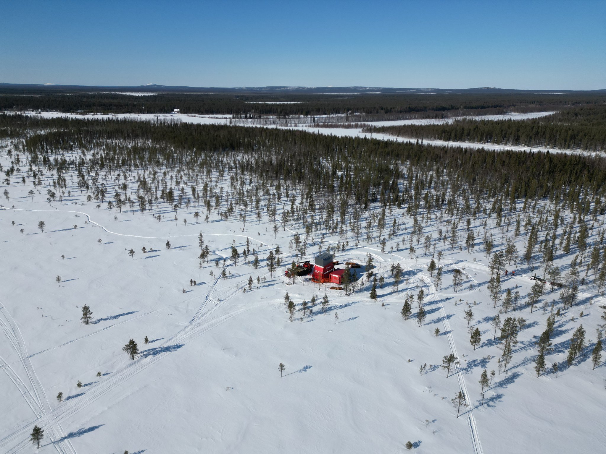
Oy Kati Ab drill rig on planned tunnel alignment in March 2024
An estimated drill hole length of 1000 m (3281 ft) was used as a benchmark, based on the assumption that the drill rigs could achieve this distance horizontally. Drilling would start near the tunnel portal area, where the tunnels are planned to be at shallow depths. This location was chosen due to its favorable geology—primarily composed of competent mafic volcanic rock—which was expected to reduce drilling complications. Additionally, the hard ground in this area allowed for easier access during autumn, when the drilling was planned to start.
The first drill hole, located closest to the tunnel portal, was started where the tunnels are at a depth of approximately 100 m (328 ft), allowing the drill to be steered along the tunnel path. Subsequent drill holes were strategically placed to provide continuous coverage along the tunnel alignment toward the deposit. It was crucial to consider that as the tunnel profile deepens, the effective drilling coverage along the tunnel’s path decreases. The final drill hole was planned where tunnels reach a depth of 550 meters (1804 ft), leaving the last kilometer (0.62 mi) to be investigated using conventional drilling, rather than horizontal.
A key parameter in directional drilling is dogleg severity, which measures the rate of directional change in degrees per 30 m (98 ft). A dogleg severity of 7° was used, as based on IMDEX’s experience, it would be a realistic value for the whole duration of the directional core drilling sections.
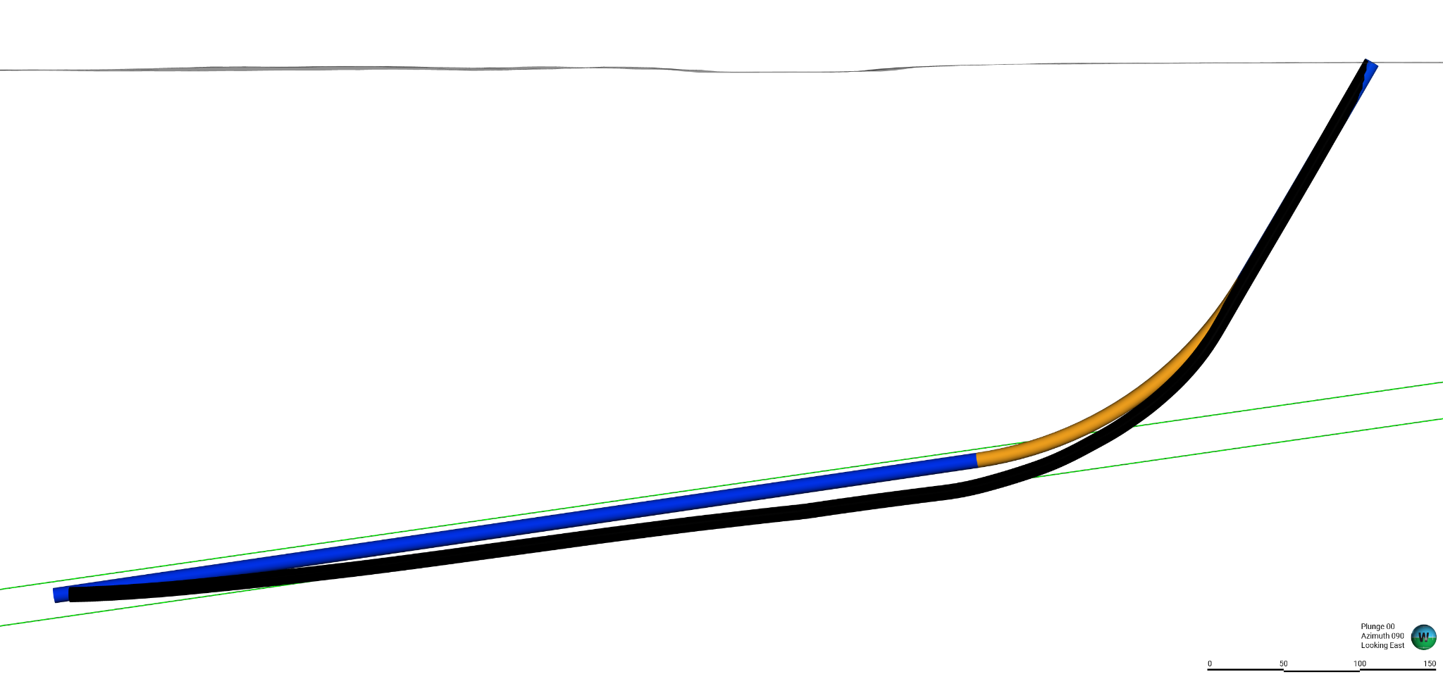 South-north section along planned tunnels, facing towards the east. Picture showing a planned drill hole (blue/orange) and a realized drill hole (black). The orange section represents the DCD section, and the blue—standard core drilling section. Planned tunnel alignment is shown in green color.
Project execution
During the drilling campaigns, Oy KATI Ab was responsible for conducting the standard core drilling, and their survey team was responsible for the downhole deviation surveys. KATI, which designs and manufactures its own drill rigs, deployed four different units throughout the program. Each rig operates with a closed-circulation system, significantly reducing water consumption and efficiently separating cuttings from the drilling fluid.
The use of drilling additives played a crucial role in overcoming challenges such as collapsing borehole walls, leakage zones, dry holes, and abrasive or clay-rich formations. These additives also helped maintain optimal fluid viscosity, ensuring effective flushing of cuttings from the hole bottom.
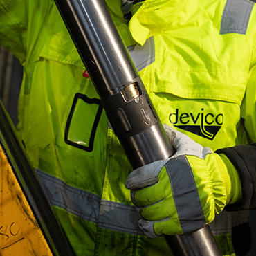
IMDEX led the directional core drilling operations. Their engineers worked seamlessly with the drilling contractor to ensure adherence to the drilling plan. This included monitoring borehole deviation, executing long directional core drilling corrections to steer the hole along the pre-planned path, and managing natural deviations during horizontal drilling.
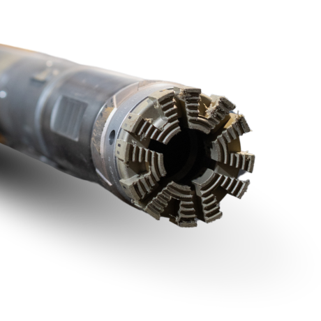
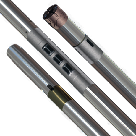
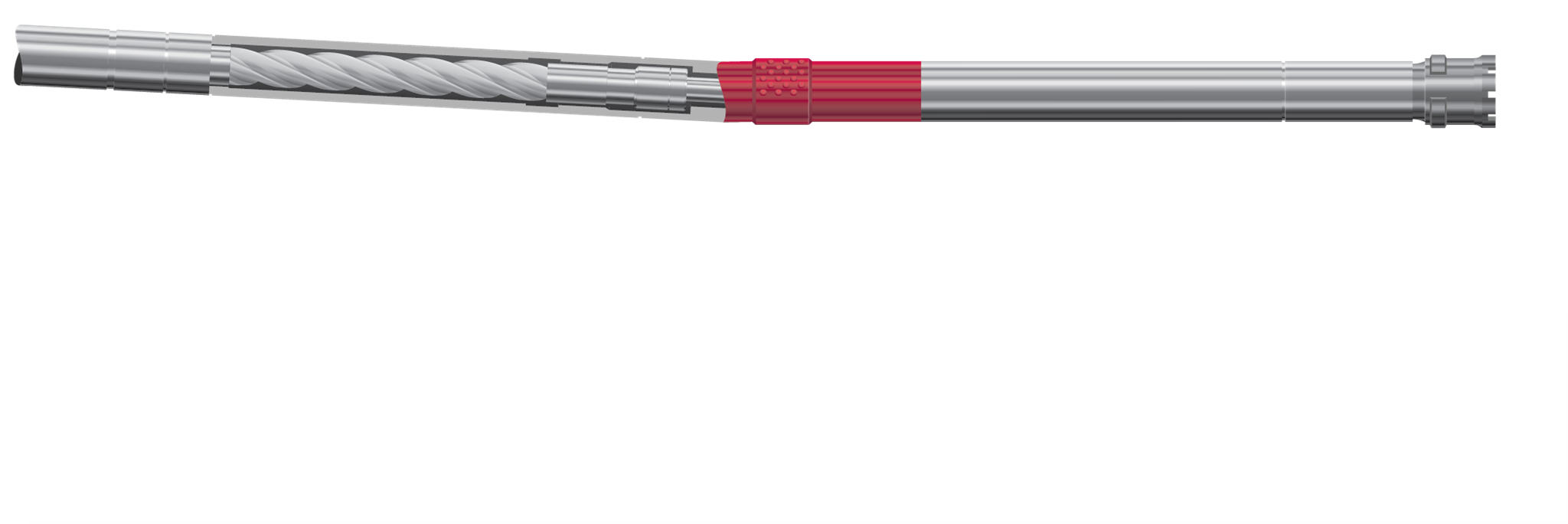
The DeviDrill™ system, used by IMDEX, integrates directly with an NQ wireline drill string and operates with the same equipment and parameters as a standard core barrel. It allows for drill hole steering while simultaneously retrieving a 31.5 mm (1.24 in) diameter core sample.
Drill hole deviation is a common issue in diamond core drilling, influenced by factors such as rock anisotropy, alternating soft and hard rock layers, rock fracture patterns, and broken rock intervals. These geological conditions directly impact the deviation rate in directional drilling sections. One of the key advantages of directional core drilling is its ability to implement corrective adjustments, guiding the drill hole back to its intended trajectory. As such, continuous monitoring and adaptive planning were essential throughout the horizontal drilling campaigns to mitigate geological factors.
The drilling program comprised of a total of six drill holes, each steered to follow the planned tunnel path in a near-horizontal orientation. Drill Holes One, Two, and Three closely adhered to their intended trajectories from the surface through the initial straight section to the kick-off point. These were followed by directional core drilling sections ranging from 170 to 220 m (558 to 722 ft), successfully guiding the holes into the designated TBM tunnel alignment with high precision.
At Drill Hole Two, an alternative approach was applied: two separate 100 m (328 ft) directional core drilling sections were interspersed with 100 m (328 ft) of standard core drilling. This method was used exclusively for that drill hole, as planning showed that a single long directional core drilling section from that collar position wouldn’t overlap precisely with the end of the first drill hole.
Once the drill holes were aligned with the tunnel path, the methodology reverted to standard core drilling. During this phase, a couple of minor directional corrections were made due to drill hole drift. Collectively, the first three drill holes contributed 2100 m (6890 ft) of exploration core drilling parallel to the planned TBM trajectory.
Valuable insights were gained during the drilling of the first hole. For instance, the importance of maintaining the pre-planned trajectory was evaluated, resulting in more frequent corrections in the horizontal section compared to later holes. Additionally, the impact of natural deviation in horizontal drilling was not fully understood before this project, as previous drill holes had been much steeper.
Drilling intersected both known and unknown fault zones. In some cases, the dip and direction of drilling allowed penetration through structures that had previously caused significant issues with almost vertical drilling. Challenging rock conditions suggested the potential need for grouting, a technique used in other projects. While core samples from standard drilling were generally solid, those obtained during directional core drilling—due to their smaller diameter—were often more fractured. However, the use of appropriate drilling additives ultimately stabilised the structures, eliminating the need for grouting.
As the tunnel profile deepened, Drill Holes Four and Five required longer straight sections before entering the main directional core drilling phase. The lithology in these areas consisted largely of disrupted zones with varying hardness, and broken rock intervals persisted throughout the directional drilling. These conditions made it difficult to follow the original trajectory precisely, resulting in extended directional core drilling sections of 200 to 220 m (656 to 722 ft). Despite these challenges and through collective efforts, the drill holes were completed within the planned tunnel path limits, investigating 700 m (2297 ft) alongside the TBM alignment.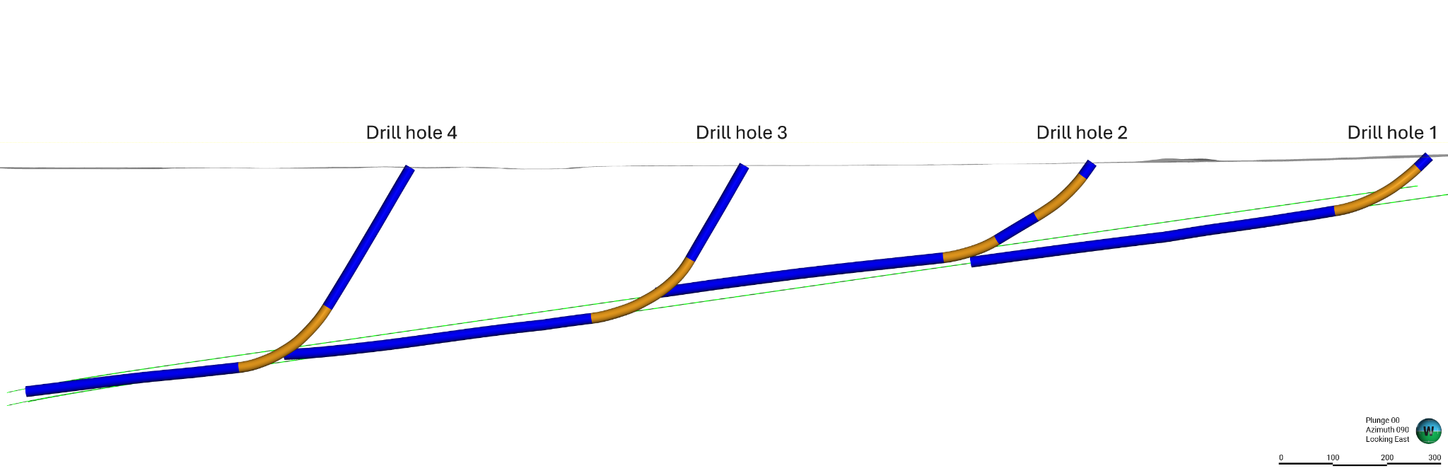 South-north section along planned tunnels, facing towards the east. Drill Holes 1, 2, 3, and 4.
The orange part of the drill hole shows the DCD section, and the blue parts—standard core drilling sections. Planned tunnel alignment is shown in green color. The true vertical depth of the end of drill hole 4 is 410 m (1345 ft).
Drill Hole Six, located closest to the deposit, was drilled in the opposite direction to the previous holes, as the tunnels were already at a deeper level. Like the others, this drill hole consisted of the same three segments—standard core drilling, directional core drilling, and horizontal drilling—but the horizontal section was executed at a slightly steeper angle.
Although this hole did not follow the tunnel path but rather intersected it, geologically, this was enough to obtain representative samples from the area.
Despite encountering highly fractured rock intervals and other geological challenges, the project successfully achieved the majority of its predefined objectives. The completion of all six drill holes yielded a total investigated length of 3000 m (9843 ft) within the planned TBM trajectory, consistently maintaining exceptional overlapping precision between each drill hole.
Conclusion
Directional Core Drilling (DCD) provides an optimal solution for tunnel investigation projects, offering precise control over drill hole trajectories. By overlapping drill holes within tunnel sections, directional core drilling allows the continuous study of the planned tunnel path, regardless of lithological complexity.
One of the key advantages of this method is the ability to obtain core samples from each directional drilling section. Gathering comprehensive data along the pre-planned tunnel alignment is essential for ensuring the safe and successful construction of tunnels.
IMDEX, with its long-standing experience in geotechnical projects, demonstrated the effectiveness of its technology and field engineer expertise throughout this campaign. Their proven, reliable systems and collaborative approach consistently ensure the successful completion of projects.
Explore IMDEX directional drilling solutions
-
Ahead of the curve

-
Product Talk: DCD methodologies
-
Product Talk: Intro to DeviDrill